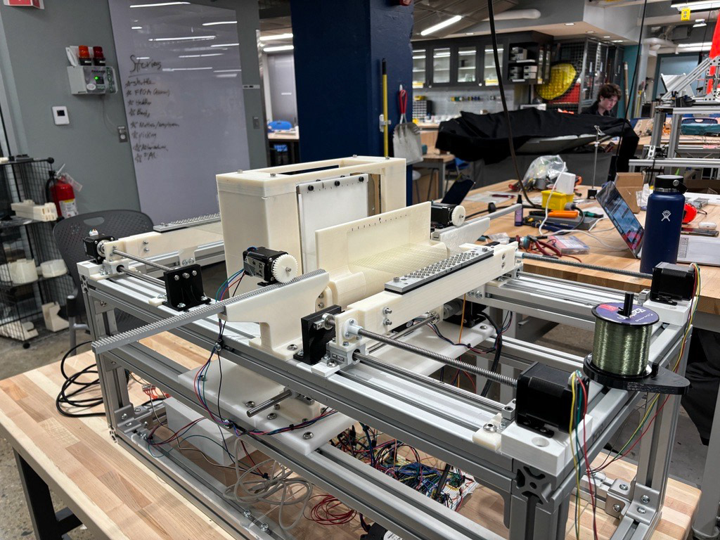
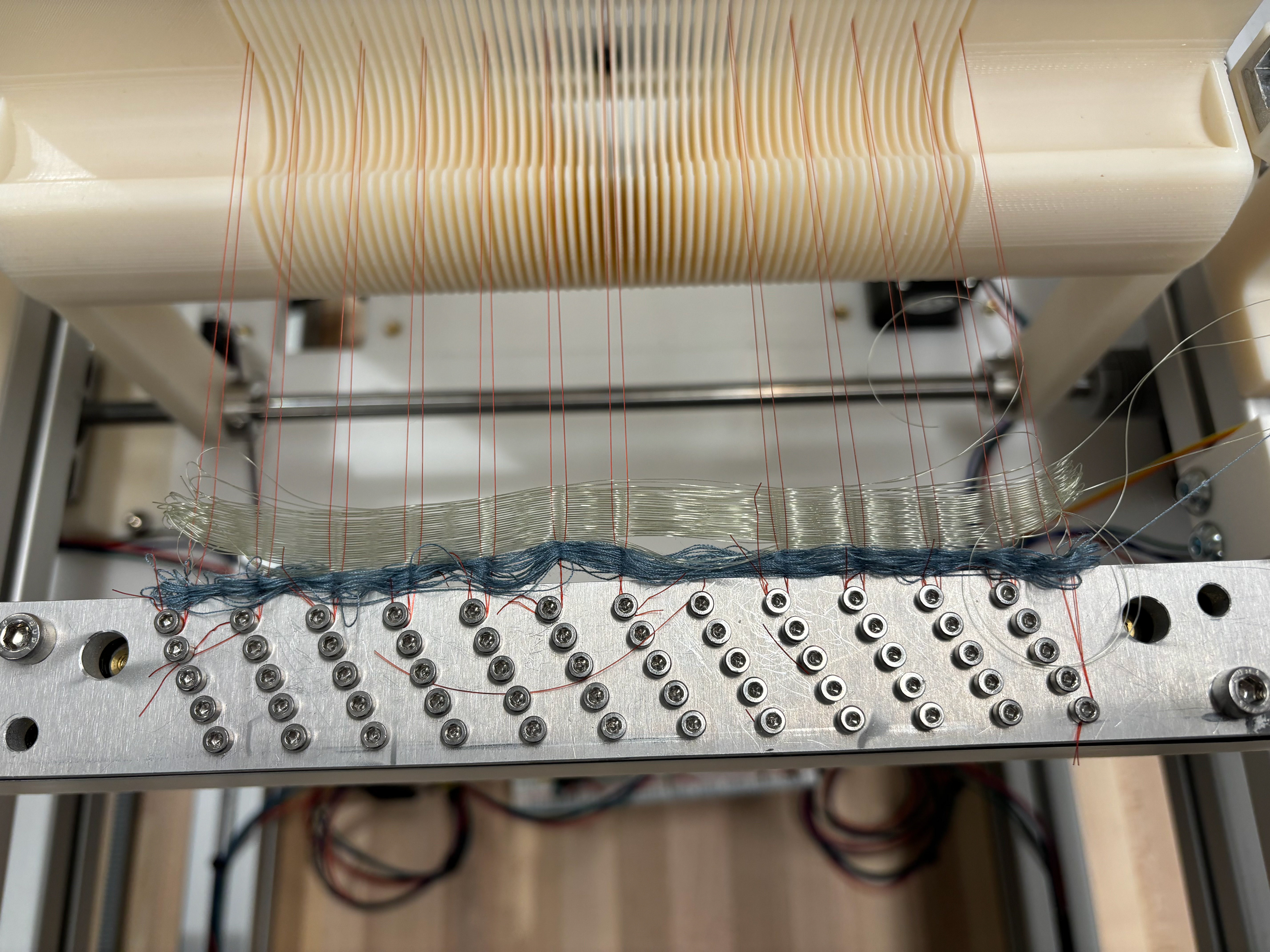
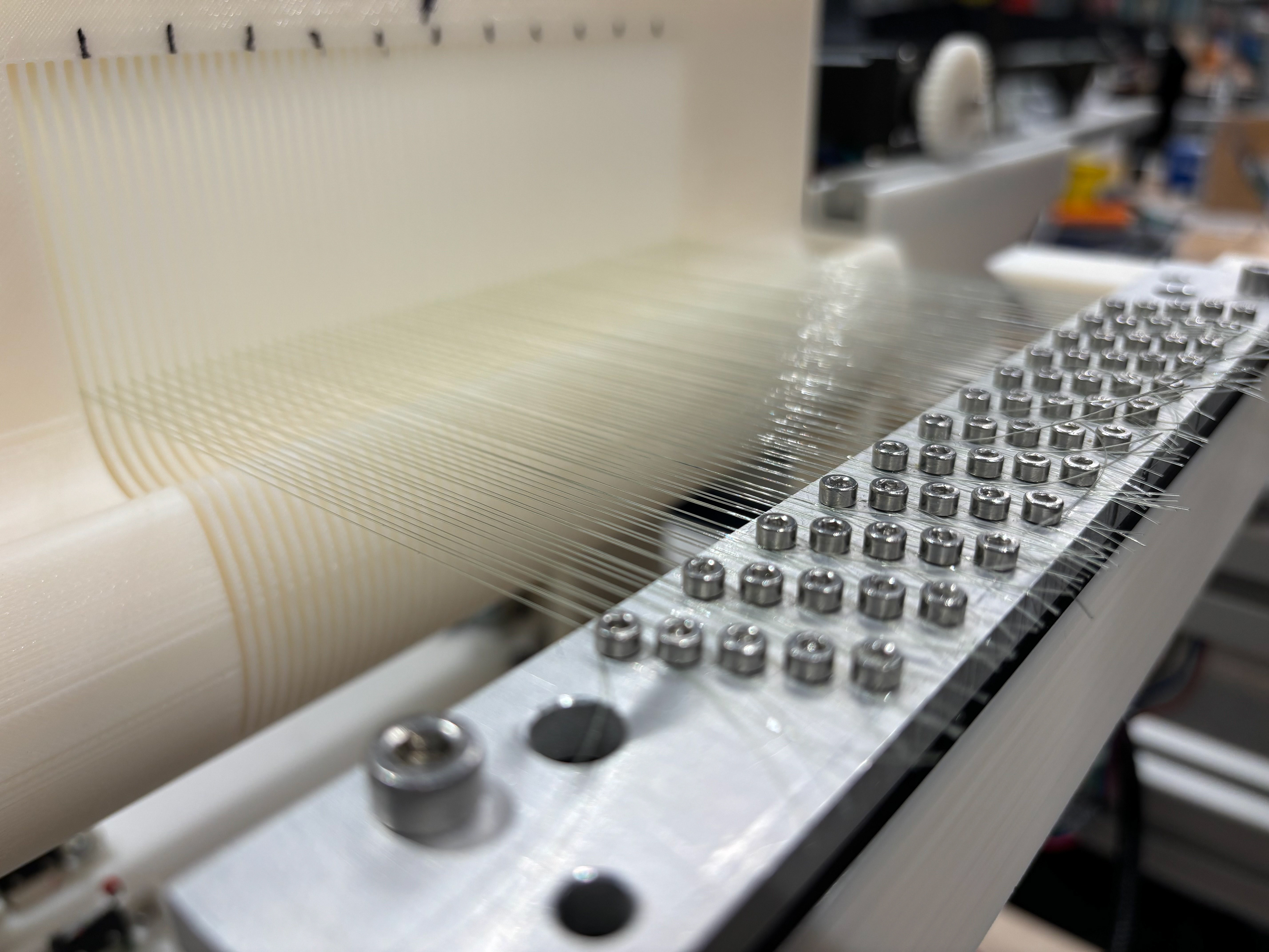
Complete weave cycle with the loom strung up at full fiber density
Background & Motivation
What Is Weaving?
Weaving is the creation of fabric by interlacing two sets of fiber, the warp and the weft, perpendicularly. The warp fibers are strung along the length of the loom and provide the foundation of the weave. The weft fibers are then interlaced across the width of the loom, to create the fabric.
You can achieve many different weave patterns through lacing the warp and weft in different combinations, each offering different properties. For our Capstone, we focused on implementing the plain weave for our prototype where the weft goes over and under consecutive warp fibers, shown in the graphic on the right.
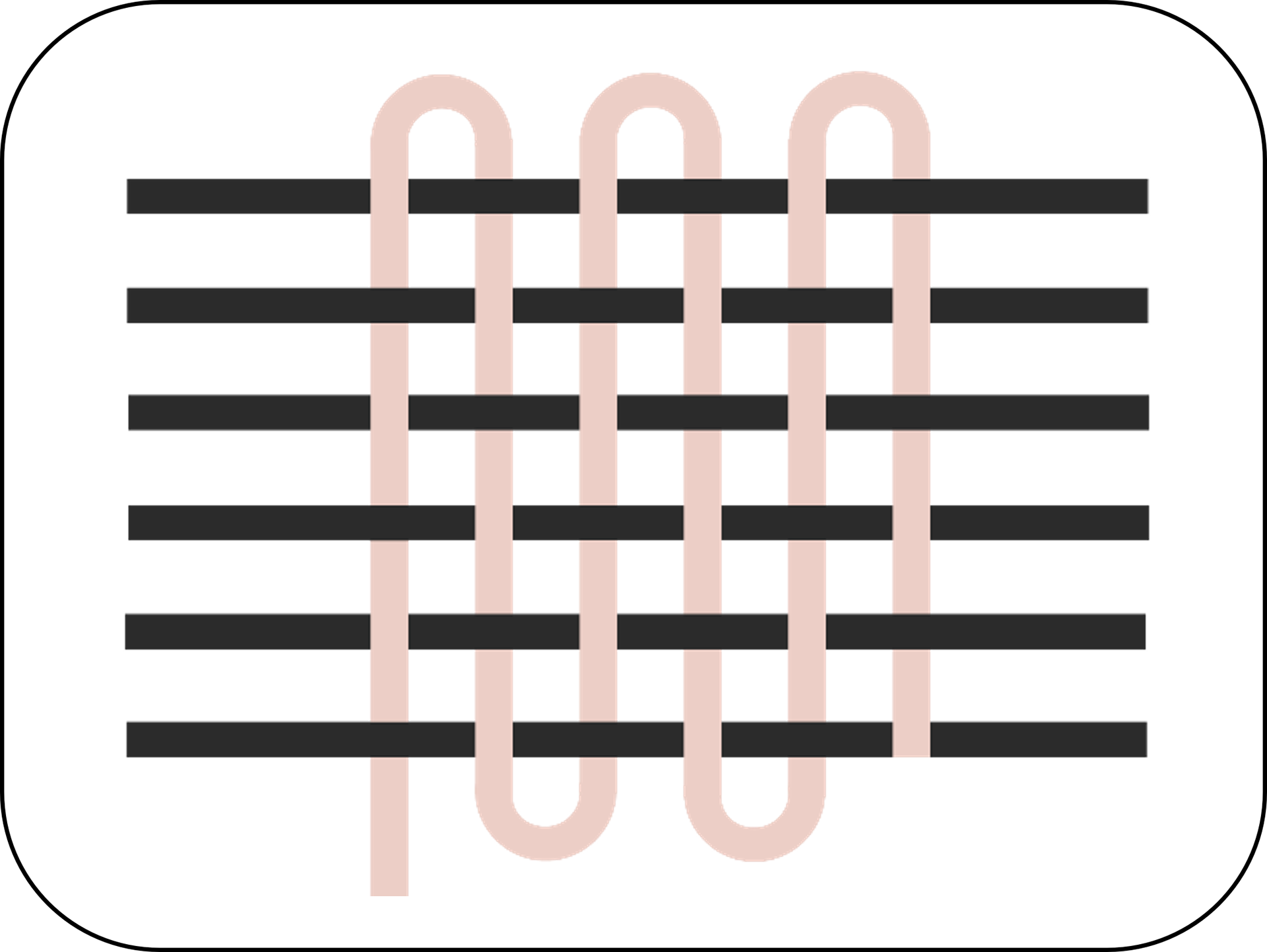
Plain Weave Pattern with the Warp & Weft
The process of weaving fabric is cyclic, comprised of four main movements
Steps
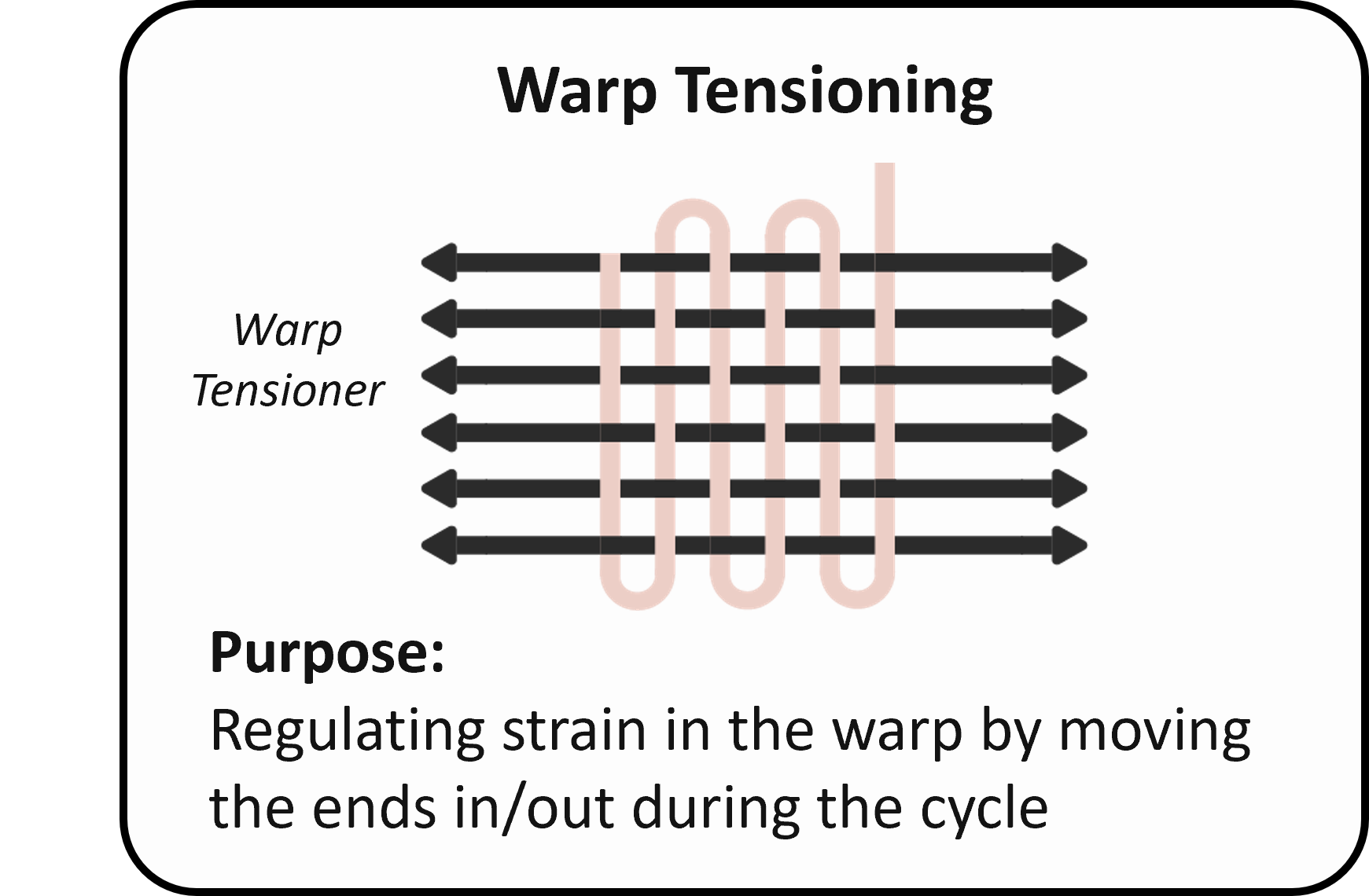
1. Warp Tensioning: regulates the strain in the fiber.
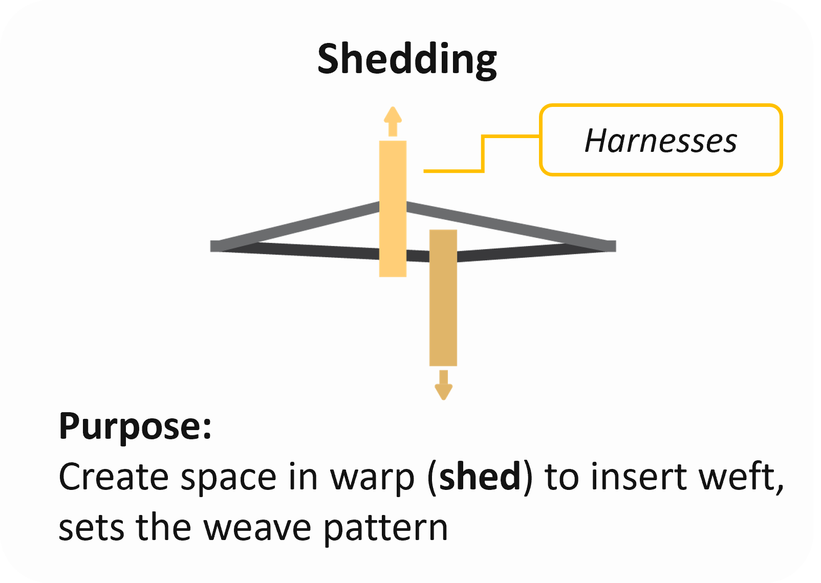
2. Shedding: warp fibers are pulled to create a diamond-shaped gap called the shed. This is done by threading the warp fibers through fixtures called heddles, which are grouped into frames called harnesses. The harnesses' movement and the number determines the weave pattern.
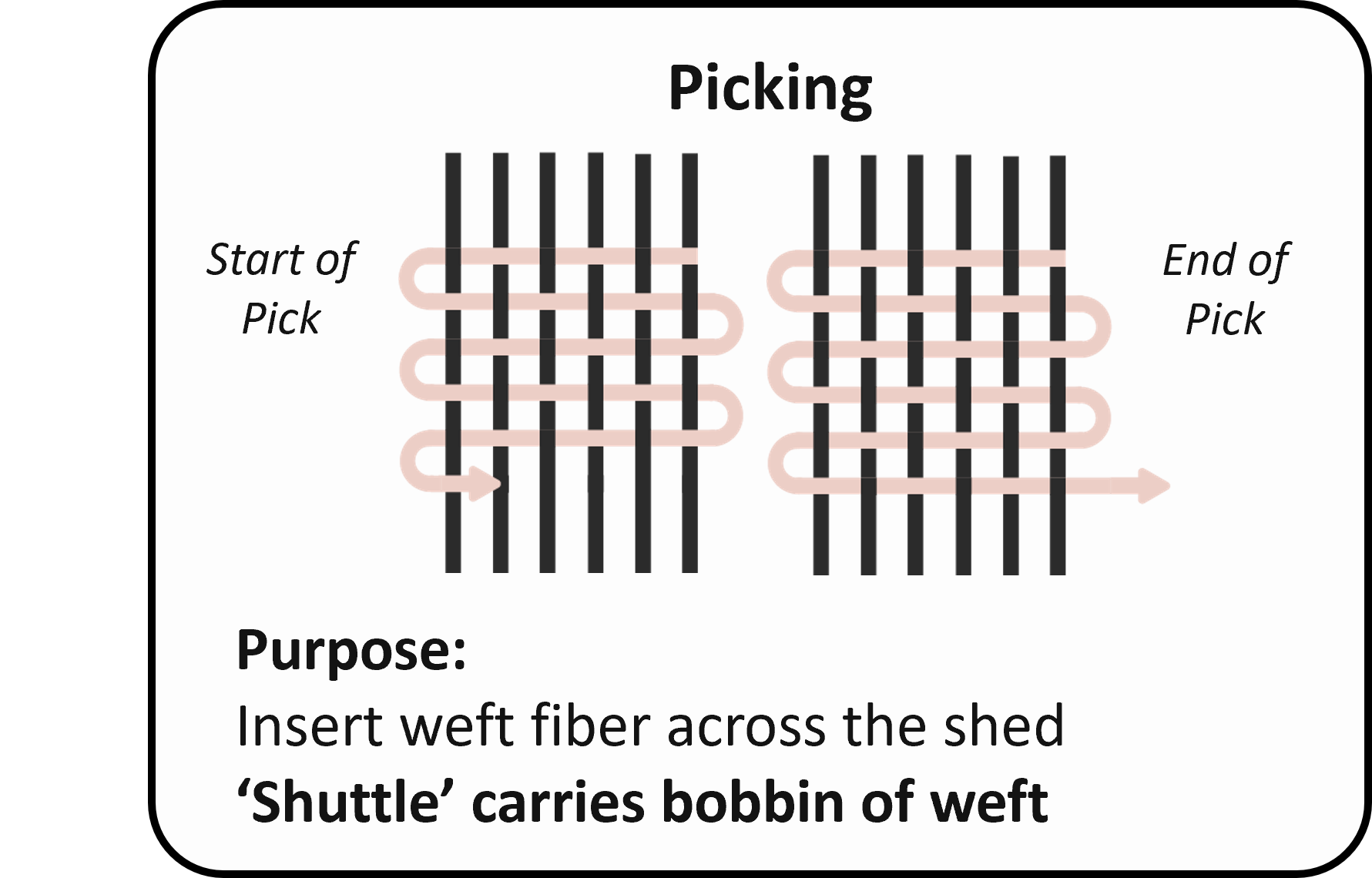
3. Picking: weft is passed through the shed.
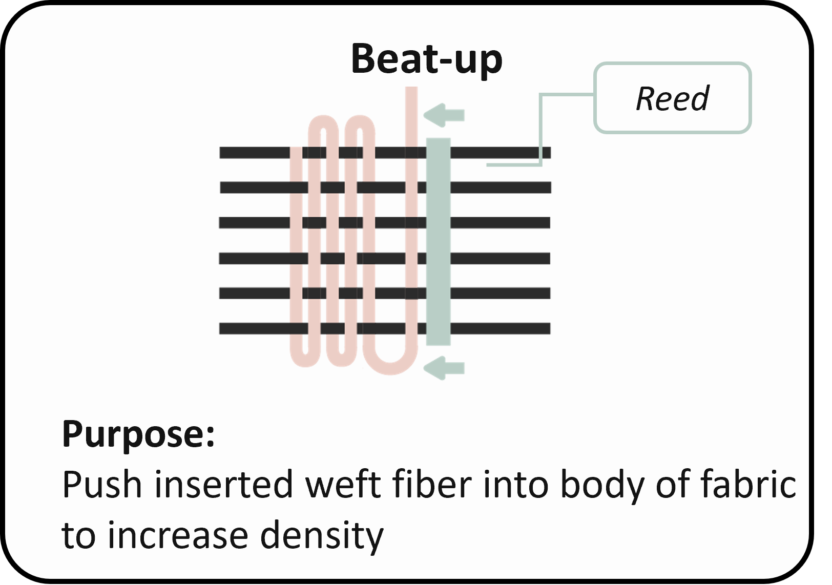
4. Beat Up: weft is pushed into the body of the fabric by a comb-like device called a ‘reed’.
History of Textile Manufacturing and
Current State of the Field
Weaving processes have been automated for mass manufacturing for hundreds of years. However, industrial-scale machines lack the precise control necessary for delicate monofilament handling and are impractically large for laboratory use.
By studying the evolution of mechanisms in industrial looms, we identified principles that we could adapt for application in the MicroLoom, namely in the warp tensioner and picking subsystems.
A Phase I Capstone team before us tried creating a machine suitable for monofilaments, providing subsystem concepts for us to reference. However, these pieces weren’t integrated because they were designed in isolation, and some key components were missing. They also battled mechanical binding and component failures once they started testing. My team and I felt these issues were significant enough to rework most of the machine from the ground up.
Applications in Textile Research
The motivation for this project was enabling Dr. Minus’ research on protective textiles for aerospace and defense applications. Her composite material is spun into monofilaments, which she needs to weave into fabric for testing.
Though weaving has long been automated, no solutions on the market are suited for monofilaments. In industry, individual monofilaments are first bundled into ‘tows,’ which are often twisted together to form yarn. Yarn withstands friction better than monofilaments because single strands can fray without compromising the whole structure.
The MINUS lab fiber is also stiffer than yarn, yielding at just 1% strain. To weave the monofilaments directly, the lab needs a machine that addresses these material constraints. We used nylon fishing line as an analog fiber to create a prototype of such a system.
Objective
To develop a proof-of-concept for an automated tabletop loom that weaves monofilament fishing line
Design Process
Mechanical Design
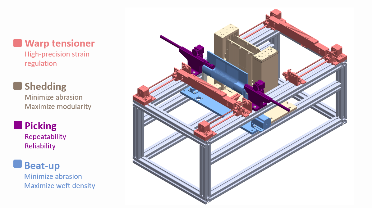
Graphic of MicroLoom with subsystem locations
Warp Tensioner
The warp tensioner design builds upon the concept developed in Phase I with an emphasis on reducing binding, improving warp strain regulation, and increasing the density of warp fiber.
During initial setup, the operator strings the warp through the reed and heddles, then uses screws to clamp the ends to the aluminum banks on either side. We attach the banks to 3D-printed carriages on either side of the frame and use NEMA 17 stepper motors with external leadscrews to drive them along the length of the loom. The leadscrews are supported at the ends by ball bearings that allow them to spin freely, and linear bearings bolted to the carriages ride along smooth shafts mounted below the leadscrews.
During each pick, the rear carriage moves in and out to control the strain induced the fiber. At the end of each pick, both carriages move together to scan the growing fabric through the machine. Synchronously driving the leadscrews and using the linear bearings as guides helped eliminate binding of the carriages.
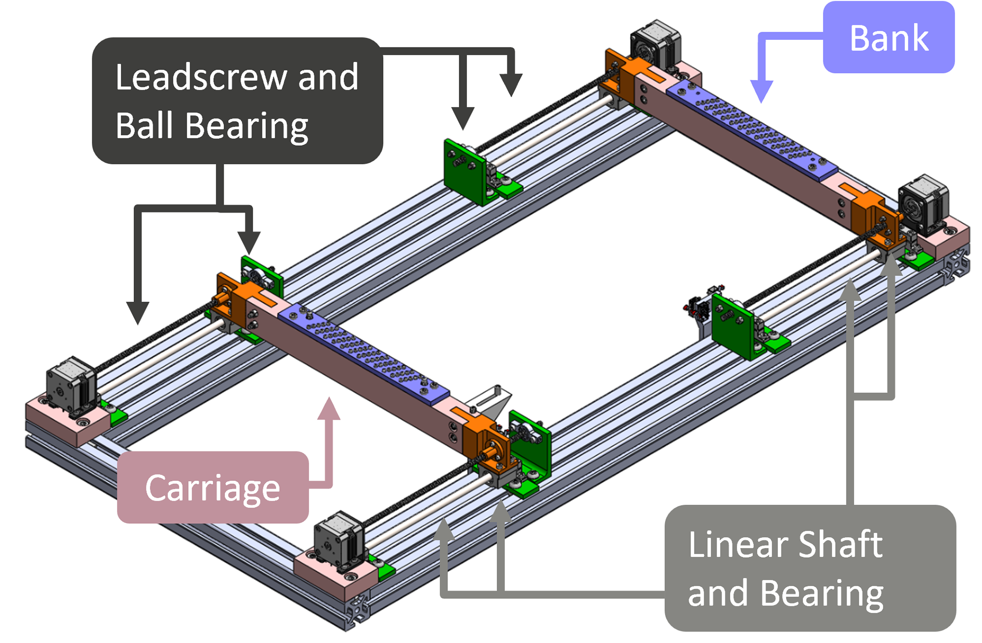
CAD model of the warp tensioner subsytem
Challenges
Designing the strain regulation procedure was the most challenging aspect of this system. Tension control was critical because opening the shed stretches the warp, and we needed to enforce the 1% strain limit of the MINUS lab fiber. We chose to do this by moving the rear bank in as the shed opens to add some slack.
To find the compensation distance needed, we used the shed geometry to develop a formula in terms of dimensions from the CAD, then built a MATLAB script to solve the equation for several hundred picks. The trajectory created by this script was fed to our motors by the Arduino control system.
Banks moving back and forth ensuring strain regulation in fiber
Shedding
While we’ve implemented two harnesses to focus on plain weave, there is capacity for up to four to enable different patterns in the future. This modularity comes from our two-piece harness construction, with swappable Delrin heddle inserts attached to an aluminum frame that gives rigidity.
Each harness is bolted to a carriage, actuated again by parallel leadscrews. Here, we use timing belts to transmit the torque from one motor to both sides of each carriage synchronously to avoid binding.
Challenges
Since we didn’t have hard speed requirements, we were able to move everything slowly to reduce the loads on our parts. This meant we could rely on 3D printing to rapidly prototype and iterate, but this came at the cost of tolerancing and surface finish, so some critical parts couldn’t be printed.
This included the heddle inserts, which had to precisely locate the warp without abrading it too much. My team worked with our machinists to find the best method and material to make them, and we ultimately chose Delrin for its low friction and found that milling produced the eyes more accurately than waterjetting.
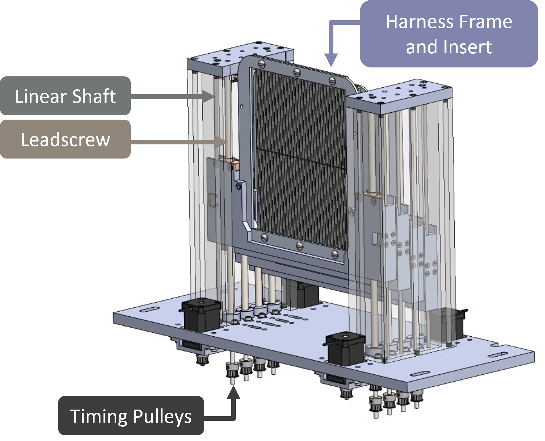
CAD model of the shedding subsytem
Picking & Beat-Up
We can consider the picking and beat up as a combined system, with the reed as the cornerstone. It serves as both the track for the shuttle and the comb to push the weft into the fabric. Slots along its width allow the warp to pass through, and unlike in conventional looms where the shuttle runs across the warp, we’ve extended these slots into the track such that there’s no abrasion. These rack and pinion linear actuators guide the shuttle through the shed, then retract to allow the shed to close.
Challenges
In initial weaving tests, we noticed issues with picking consistency. The weft resisted unspooling, and the extra tension caused the shuttle to get stuck or fall of the track. The shuttle was also prone to getting misaligned and getting caught in the warp. Iterative design was required to solve these problems; using 3D printing, we tried different geometries and bearing placement strategies to secure the shuttle on the track and improve unspooling. We also switched from a printed bobbin to a metal dowel, finding that the larger bend radius helped the fiber unwind.
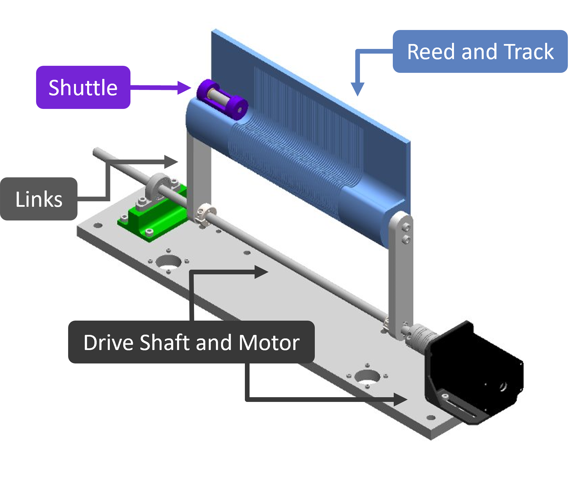
CAD model of the picking/beat-up subsytems
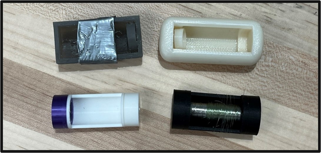
Iterartion of Shuttle Design
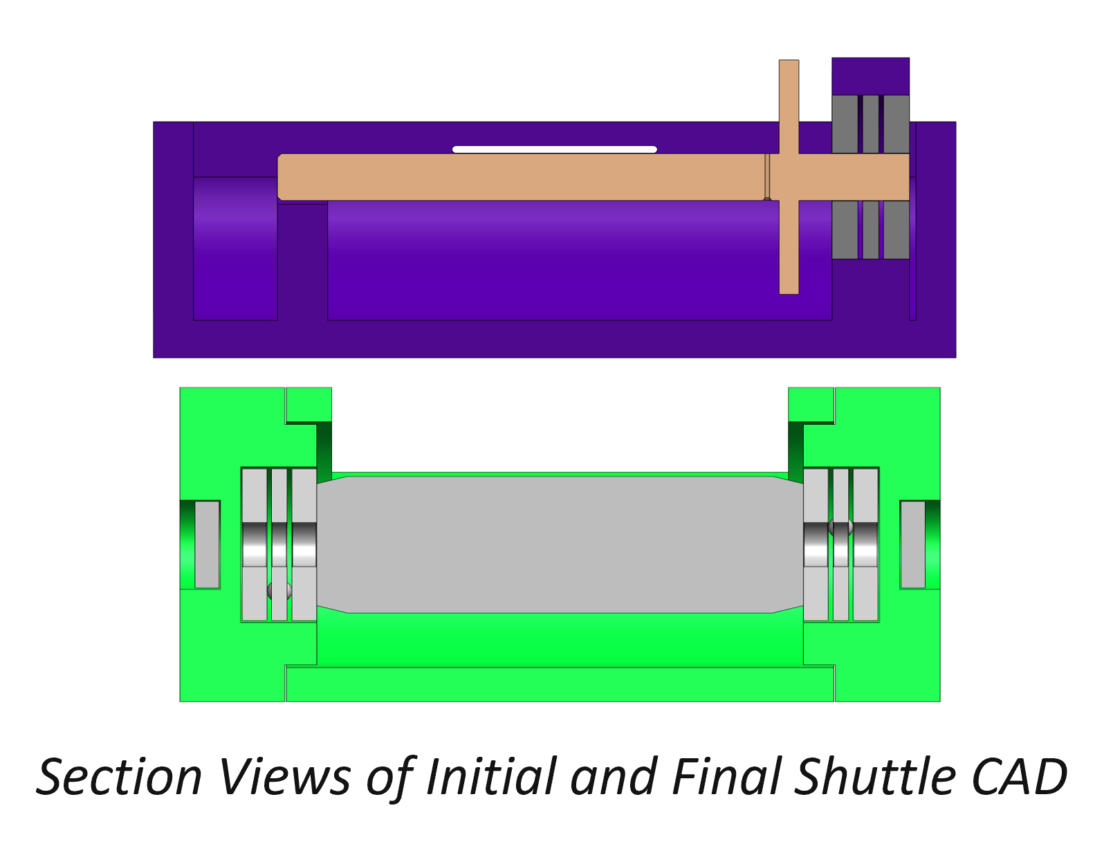
Initial Shuttle Design (top) & Final Shuttle Design (bottom)
Control System
Electronics
The full circuit developed to actuate the loom includes an Arduino MEGA, 9 stepper motors and drivers, 5 limit switches for system homing, an emergency stop, and a 12V power supply unit.
Code
The mechanical and electrical systems are bridged by an Arduino control script, which has 2 main components – homing and weaving. Both are controlled by a user pressing a different button. The homing sequence sets reference positions for each subsystem with limit switches and is a crucial step since it allows for us to string up the loom at the correct starting point. After homing, the user can turn off the system, string up the loom, then turn it back on and start weaving.
Challenges
A core bottleneck in our control system involved finding the right stepper driver. The chips used in Phase I are easy to program, but they required 3 digital pins each. With so many motors, we risked exceeding the capacity of one Arduino. After consulting with engineers from Amazon, we learned that linking Arduinos would significantly increase software complexity, so we decided to source new drivers that require just one pin when programmed with a protocol called SPI.
While learning how to implement SPI, we first built a test circuit on the bench and worked up to controlling all 9 motors. This gave us the confidence to mount the motors to the machine and begin subsystem testing.
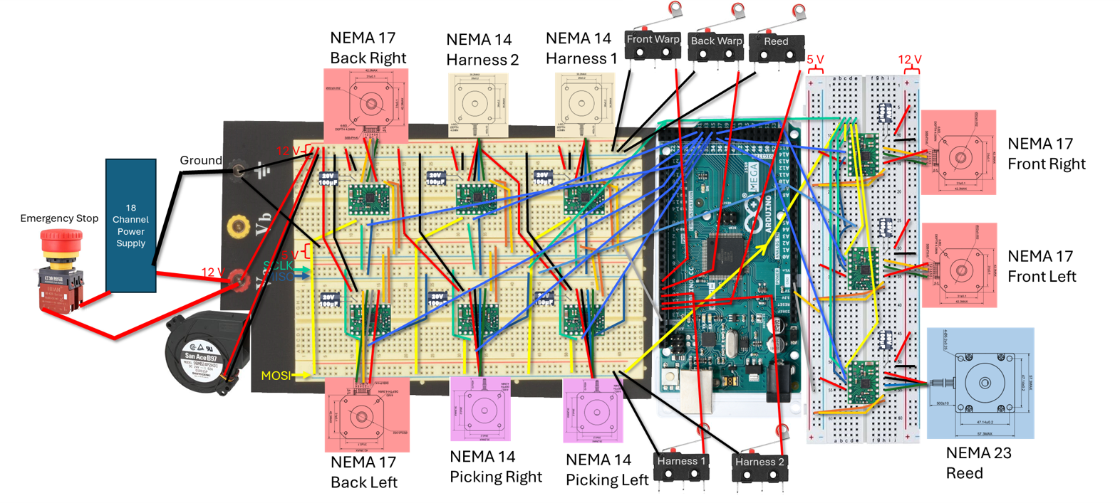
Electrical schematic of the control system
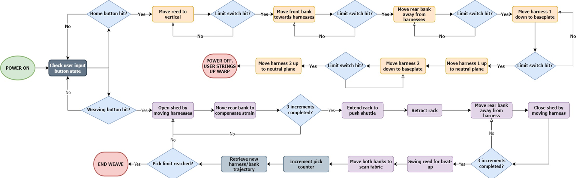
Process flow diagram of the control system
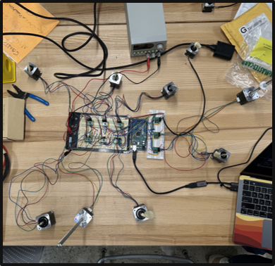
Test Circuit with SPI
Takeaways
In the final design of the loom, my team and I demonstrated reliable homing of all subsystems and performed extensive cycle testing of the weaving motions, seeing no binding issues. Each pick takes 19 seconds, and fully stringing the loom takes 2 people approximately 3 hours.
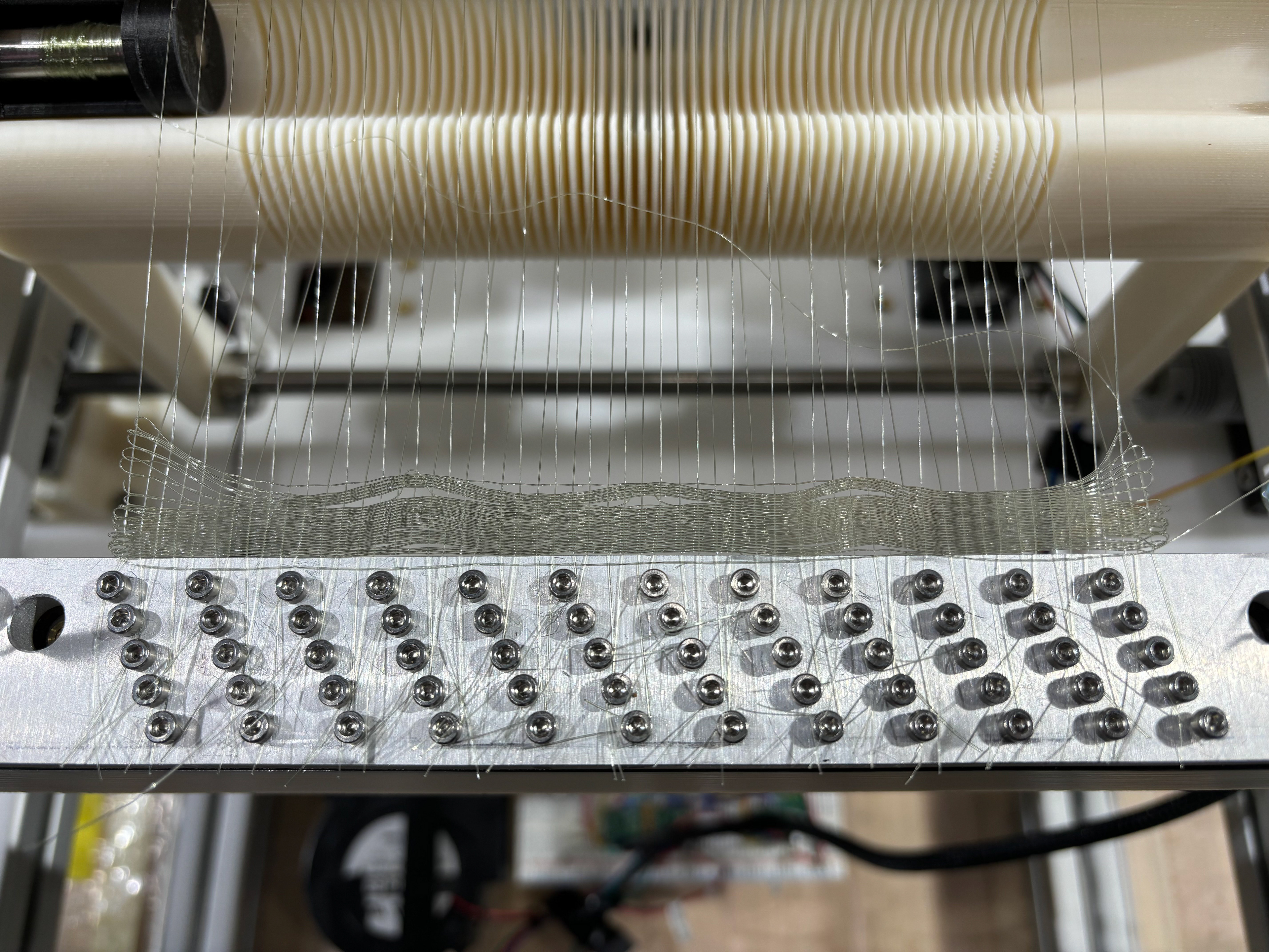
We then ran full weaving tests, experimenting with the warp density to evaluate its impact on the product. Our goal was to make patches at least 1 inch by 1 inch, up to 36 inches squared. With low warp density across the 6 inch width, we were able to create a weft-dense patch of fabric that met our target of 100 picks per inch of length. When we fully strung the warp, we obtained a weft density of 13.6 picks per inch.
These results showed that monofilament weaving at the lab-scale is feasible!
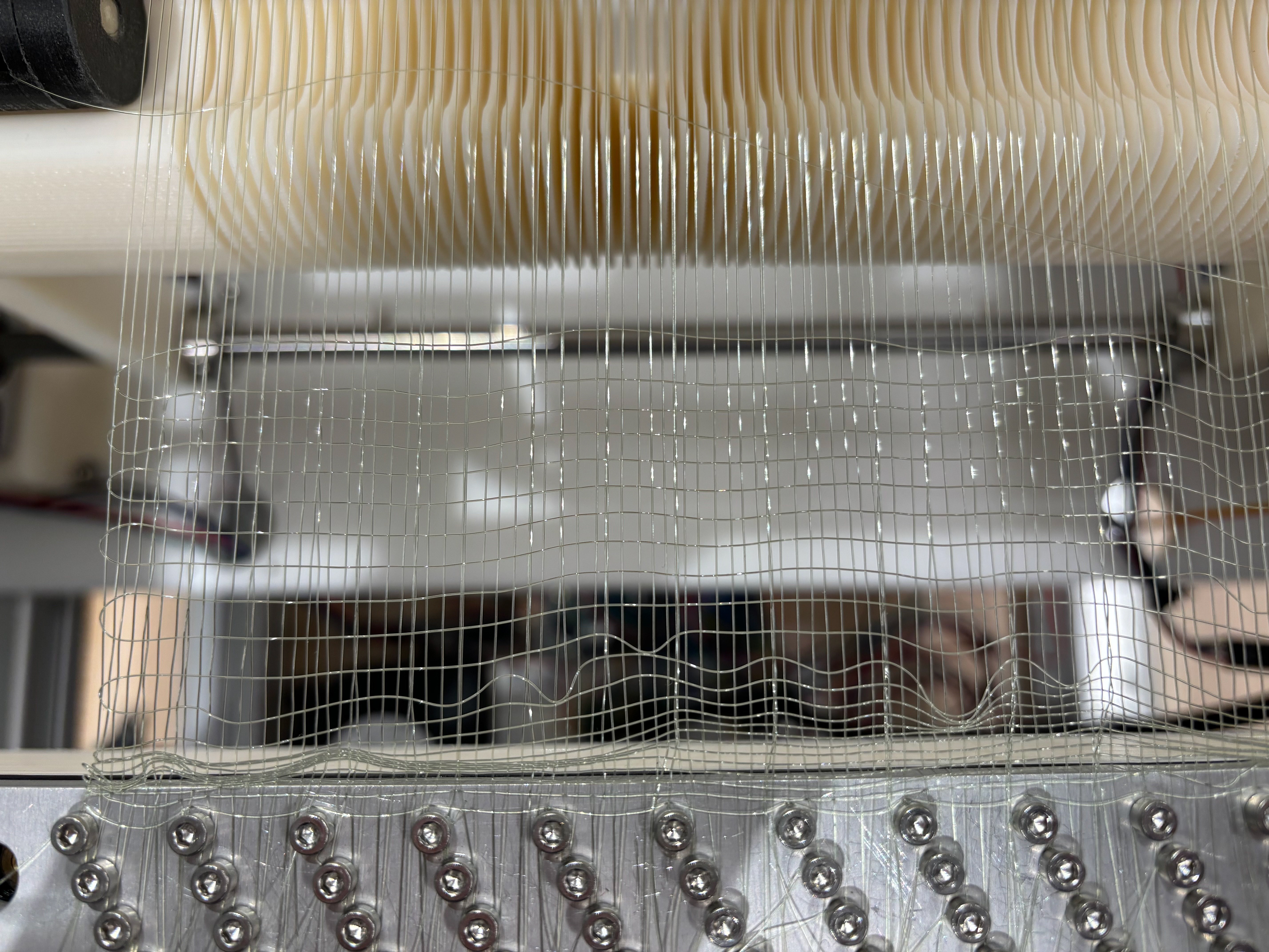
Full Density ("Warp Dense") Fabric
50% Density Fabric
"Weft Dense" Fabric
Future Work
Though we delivered a successful proof-of-concept device to our client, my team and I recognized areas where our system can improve.
1. Strengthening the beat-up mechanism: the reduced weft density in the second patch was due the beat-up system not having enough torque to overcome the stiffness of the fabric when we added more warp ends. Though we believed we oversized our beat-up motor in the initial design phase, we did not have a reliable way to analytically estimate the required torque. Based on our experimental findings, future development of the MicroLoom should focus on strengthening this system, potentially through a gearbox.
2. Micromachining to equip the machine for long-term use with the lab’s smaller and stiffer fiber
3. Activating the two remaining harnesses to allow testing of other weave types
Project Gallery