Task Workspace of the 3R Robotic System
Background
I completed this project for a robotics course I took during my last semester at Northeastern; It allowed me to exercise knowledge in dissecting a physical robotic system through homogenous transformations, inverse kinematics, and trajectory planning, and developing a electro-mechanical robotic system complete with modes of actuation (eg. stepper motors) and control schemes (eg. PID).
Objective
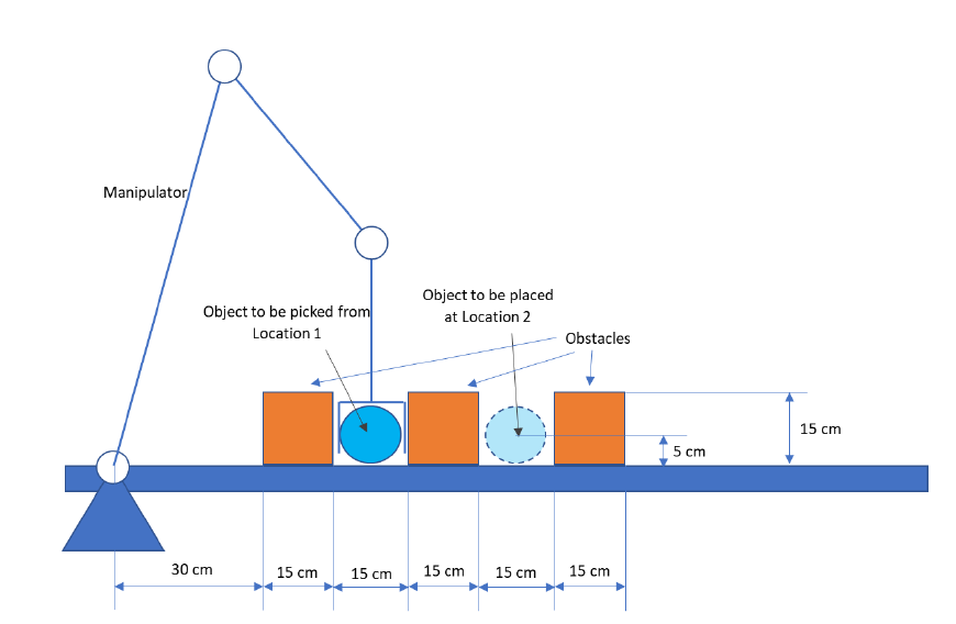
The goal of this project was to design this robot so that it can perform a pick-and-place task from Location 1 to Location 2 without touching the orange obstacles in the environment as shown in the image above.
Variables, Assumptions, and Design Constraints
1. The dimensions of the robot were given as: 100 cm, 50 cm, and 40 cm for Links 1, 2, and 3, respectively.
2. It's assumed that the object to be picked up is a sphere with a diameter of 10 cm, and that the gripper is small enough that it can go in between the obstacles without touching them.
3. The robot can't touch the obstacles at any point during the pick-and-place task, and the 3rd Link must reach a vertical configuration at the time of pick up and drop off.
Design Process
The project was divided into 2 parts
Part 1
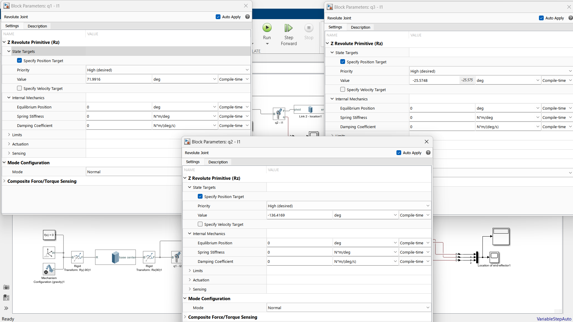
The first part of the project focused on analyzing the robot with inverse kinematics to find the angle measures of each link (q1, q2, q3) that are needed to perform the pick-and-place task while adhering to the design constraints mentioned above.
↓ What I did ↓
• Created a MATLAB script that calculated the link angle measures using inverse kinematics at the pick up and drop off locations
• Built a physical model of the robot in Simscape, input the angle measures into each revolute joint of the links, and simulated the robot's geometry at the start and end locations of the pick-and-place task
Code for Part 1 including Inverse Kinematics
Part 2
Continuing off of the work done in Part 1, the second part of the project focused on building a trajectory for the robot travelling from Location 1 to Location 2 and applying it to a complete electro-mechanical robotic system in Simulink.
↓ What I did ↓
• Built MATLAB code that created a string of angle values for the links as it moves from the pick up to the drop off location
• Expanded the physical model of the robot in Simscape to include DC motors and power supplies that drive each link, converting the angle measurements into torques and voltages, and simulated the robot completing the pick-and-place task
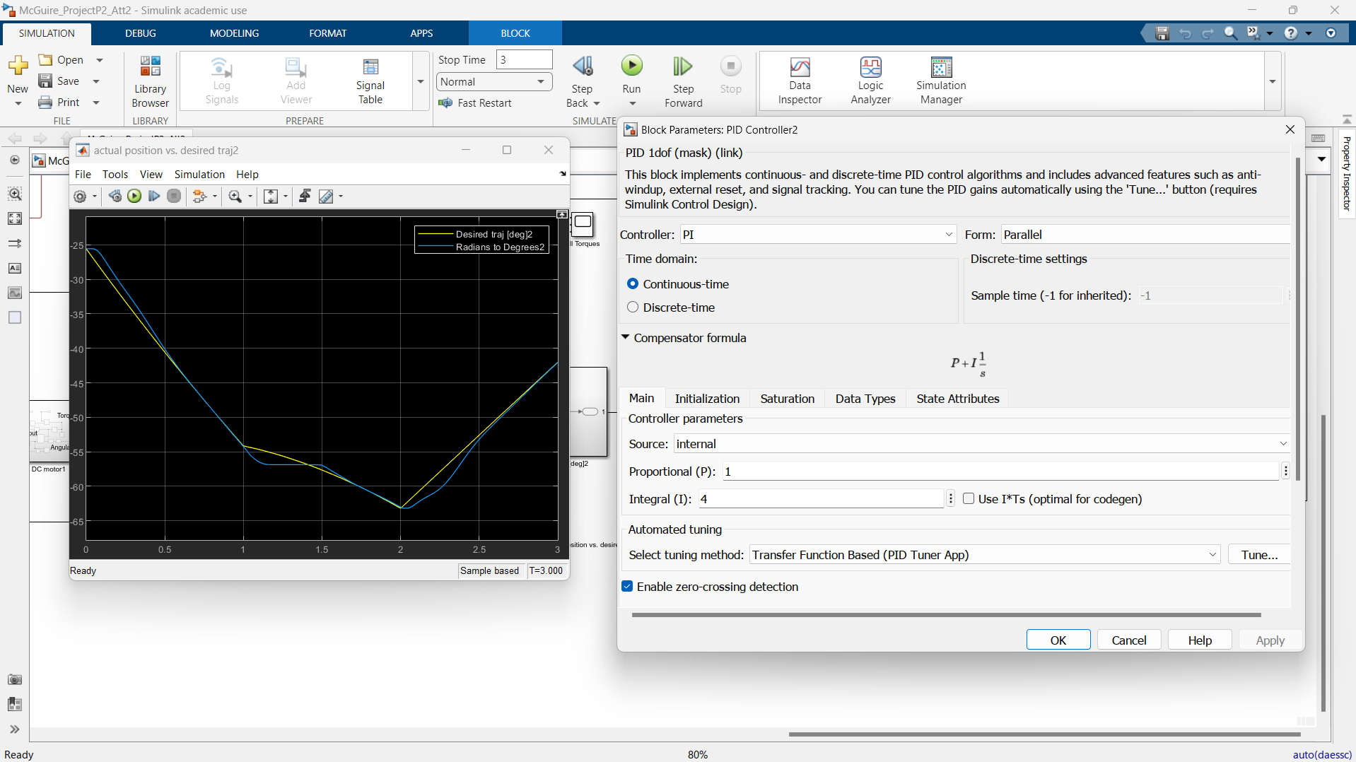
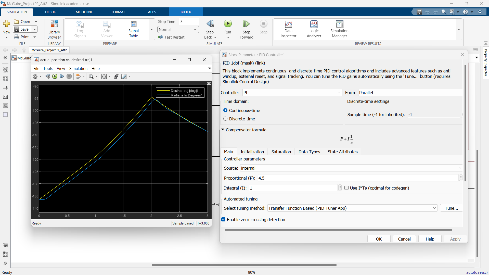
• Incorporated closed-loop control with PID control to tune the "actual" or experimental angle values so that they are closely aligned with the desired angle values
Code for Part 2 including Trajectory and Inverse Kinematics function
Final Result
Through completing each part, I was able to simulate a 3R robot completing the pick-and-place task and satisfies the design constraints.
What I Learned
• How to build a robotic system in Simscape complete with physical components and electronics
• How to analyze a robotic system with inverse kinematics using MATLAB
• Path-planning and building a trajectory using MATLAB
• Understand the relationship between mechanical and electrical quantities in the context of driving robotic systems
Pick-and-Place Simulation (Desired Behavior)
Skills Developed
• MATLAB
• Simscape & Simulink
• Analyzing robotic systems
• Controls and implementing closed-loop feedback
Pick-and-Place Simulation (Actual Behavior)
Project Gallery
Location 1 "Pick Up" Angle Measures
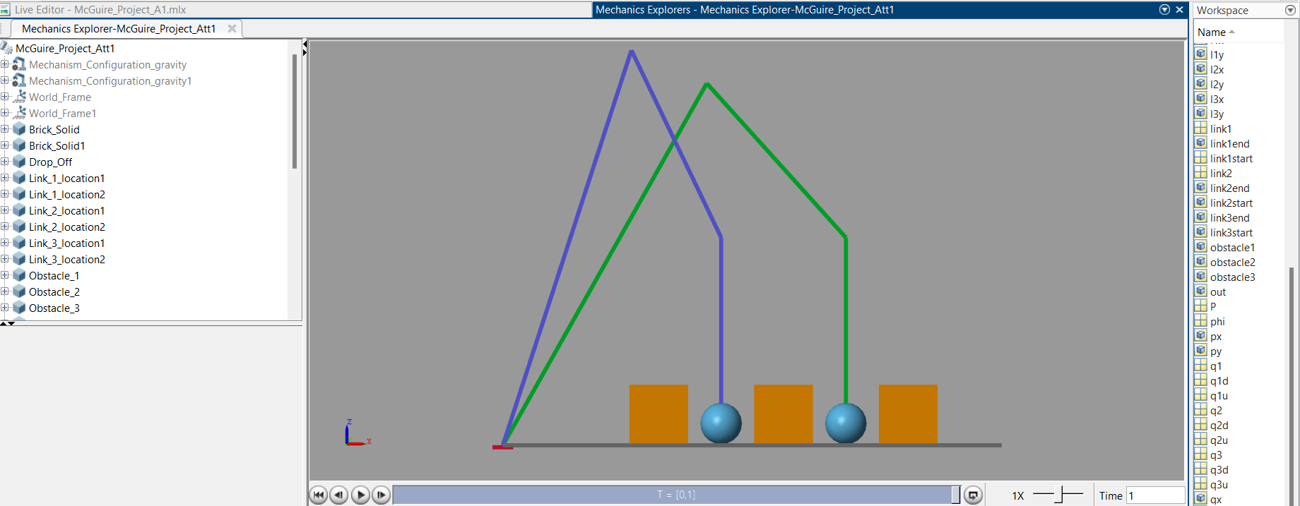
Simulation of Robot Geometry (blue = location 1, green = location 2)
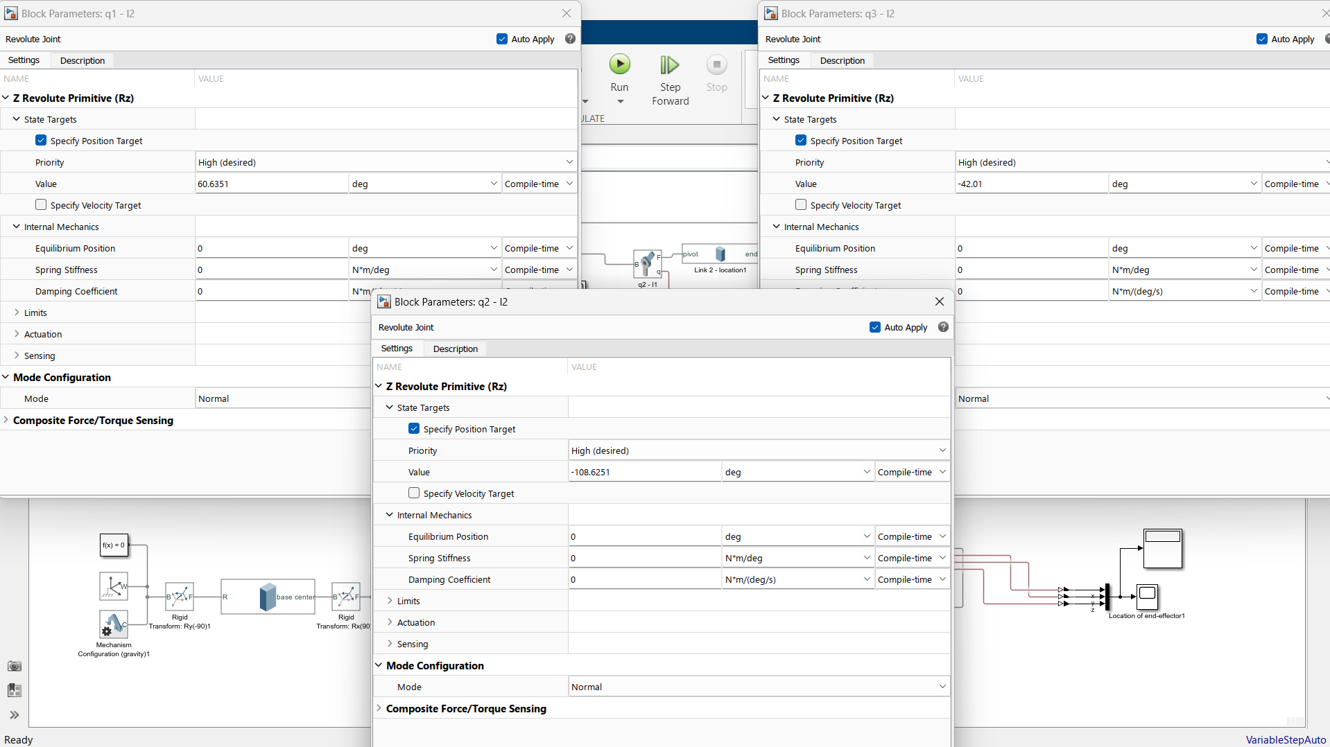
Location 2 "Drop Off" Angle Measures
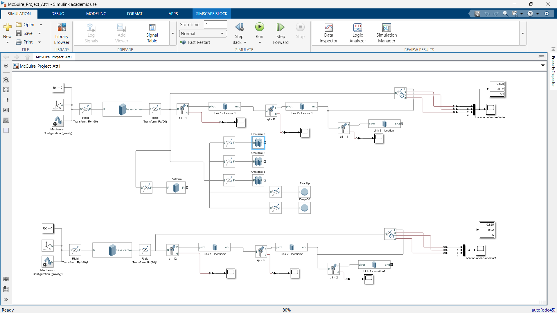
Simulink Model (Part 1)
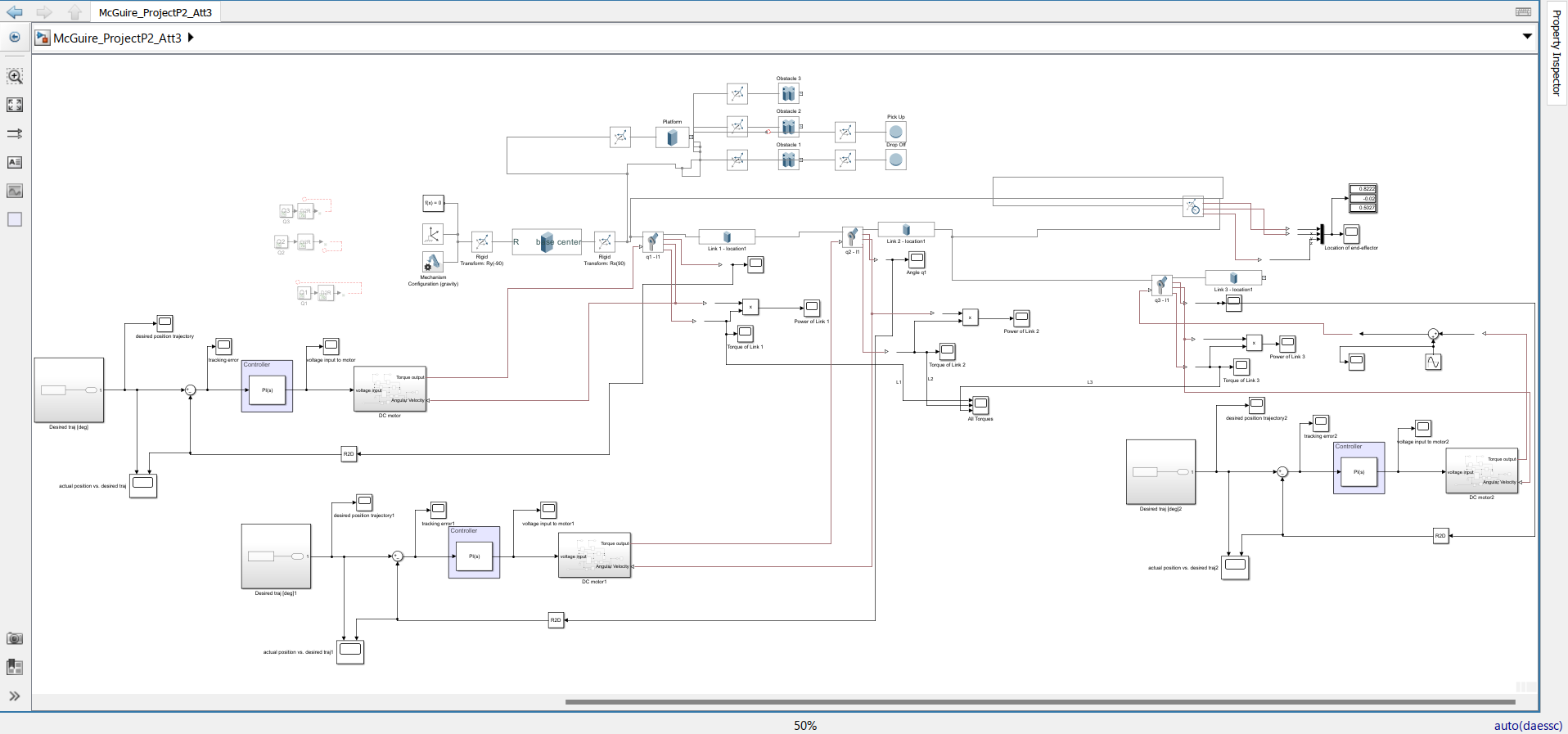
Simscape Model of 3R Robot with DC motors and Closed-Loop Control
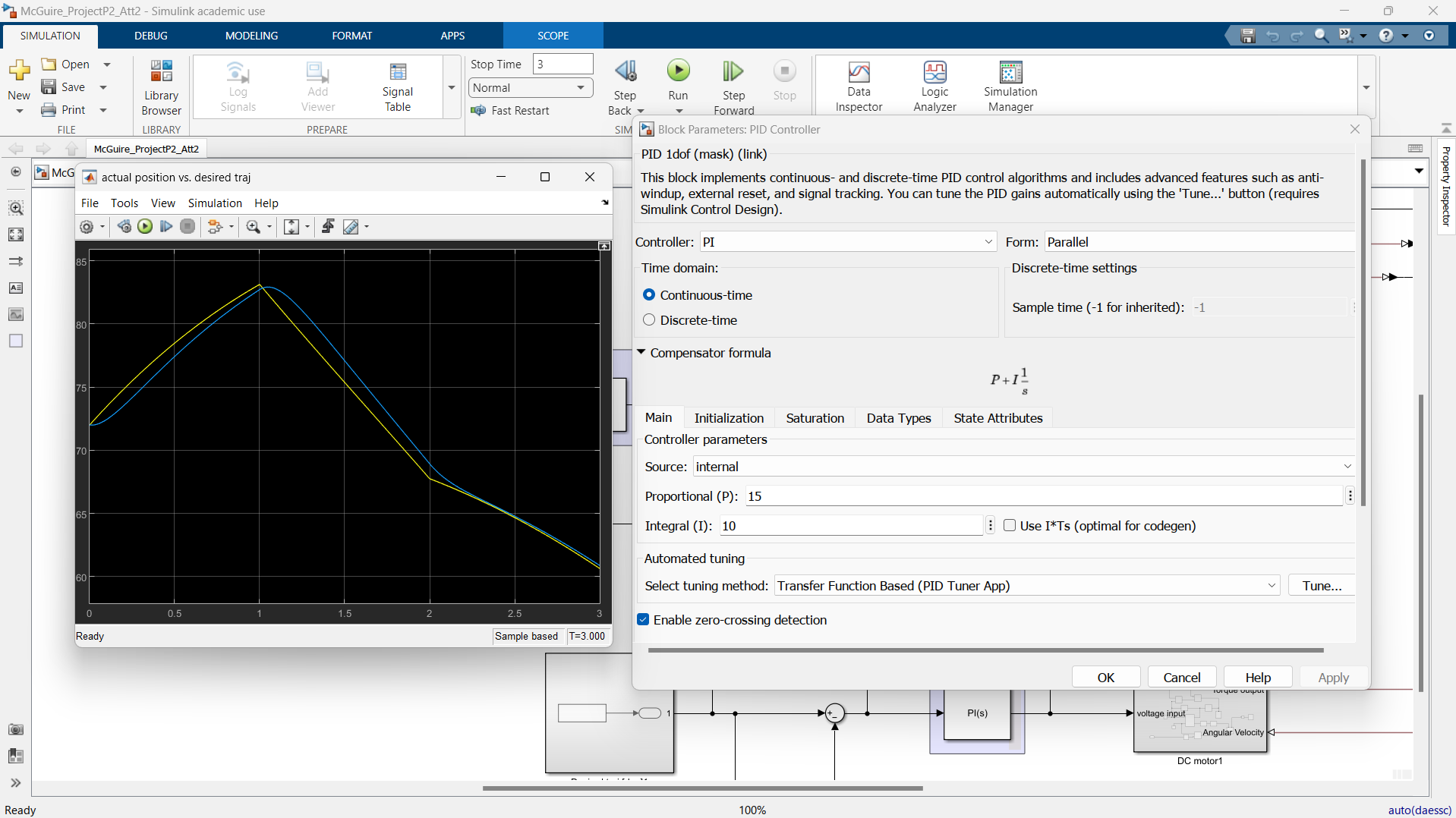
Actual vs. Desired Trajectory for Link 1 (theta vs. time)
Actual vs. Desired Trajectory for Link 2 (theta vs. time)